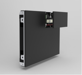
Produce Taste regulation grid Book
SPECIFICATION
Product Name : Outdoor large display P3 thirteen-scan module
Product Model : Q3.0 -13S-1515 Plus (DPS)
Document Number :
Version number : 1.0
Drafted by: | Reviewed by: | Approved: (Official Seal) |
Company Address: Qiangli Jucai LED Display Industrial Park, No. 5 Yutashi Road, Xiang'an Industrial Zone, Xiamen Torch High-tech Industrial Development Zone, Fujian Province
Customer service hotline: 4001001222 Telephone: 0592-7885 888
Email: led@qlled.com Fax: 0592-7885656
Website: www.qlled.com Postal code: 361100
Table of contents
4. Product Technical Requirements
6. Product Model Naming Instructions
7. Installation Hole Position Diagram
1. Scope of application
This technical manual applies only to the outdoor large display Q3.0-13S - 1515 Plus (DPS) module . The following are the parameters for the standard product. Customization is available for special requirements.
2. Precautions
project | describe | |
environment Notice matter | Temperature requirements | Storage temperature range: -10℃ to 30 ℃. Cooling is required if the temperature exceeds 30℃. Operating temperature range: -20℃ to 40℃. For other temperature ranges, a temperature control device needs to be installed. When the module is working, the lamp surface temperature should be ≤85℃. If the temperature exceeds the limit, a temperature control device needs to be installed. |
Humidity requirements | Storage humidity range: 10%RH-60%RH. If the humidity exceeds 60%RH, dehumidification is required. Operating humidity range: 10%RH - 90%RH. If the humidity exceeds the standard, the environment must be dehumidified before normal use. | |
Corrosive gases | Corrosive gases in environments containing salt or acid can cause corrosion, crystallization, and leakage of electronic components. | |
Static electricity hazards, prevent lightning strikes | The metal components of the screen, the casing of the switching power supply, and the enclosure must be properly grounded. Note that the grounding resistance should be ≤ 10 Ω and the neutral-to-ground voltage should be ≤ 2V . This is to prevent static electricity from damaging electronic components and to avoid leakage current from harming the human body. | |
use operate Notice matter | Electrostatic protection | Installation personnel must wear anti-static wrist straps and gloves, and all tools must be strictly grounded during the assembly process . |
Waterproof screen | After the entire screen is installed, it is essential to ensure that no water enters the interior of the screen. Waterproof sealant should be applied around the screen, and at the junctions between the cabinets to ensure proper waterproofing . | |
Hazards of magnetic installation method | It is not recommended that customers install the module outdoors using magnetic mounting, as outdoor installation may cause the following hazards: 1) Rain and snow can enter from the front of the display screen to the back of the display screen, causing the electronic components, system cards , switching power supplies and cables on the module IC side to be soaked and corroded, leading to premature failure ; 2) Magnetic installation cannot guarantee the flatness of the display screen and the assembly effect; 3) Magnetic installation can easily cause the module to deform in extremely cold weather . | |
Product batch number control | Products from different batches cannot be displayed on the same screen; otherwise, color blocks (mosaic) will appear on the screen . | |
Product wiring | The module cannot be directly connected to 220V , and the positive and negative terminals of the module power supply cannot be reversed . | |
Disassembly and transportation process | Do not drop, push, squeeze, or press the module to avoid damaging the display screen . | |
Install torque control | , ensure that the terminal screws are tightened to prevent the connector from becoming loose, which could lead to high contact resistance and cause wire burnout or product damage. The torque for M4 screws is 6.0-8.0 Kgf.cm , and the torque for M3 screws is 4.0-6.0 Kgf.cm. | |
Playback Control | Please do not display static images or text for extended periods, as this can severely reduce the brightness of the LEDs or cause a large number of LEDs to fail. Please play scrolling images or text instead . | |
Live work is prohibited | It is forbidden to assemble the module while it is powered on. The module should be assembled on the wall with the main power input disconnected. It is not allowed to assemble the module with the power cord and signal cable inserted . | |
Loader selection | by the official website of Qiangli Jucai and the loading program in the one-click debugging section of the official website are required to avoid performance anomalies during the debugging process. | |
Parameter settings | The refresh rate must be set according to the value specified in the datasheet to protect the normal lifespan of the lamp . | |
Playback Control | Please do not display static images, text, or fixed backgrounds for extended periods, as this may cause severe brightness degradation of the lamps or lead to mass lamp failures. Please use scrolling images or text instead. | |
Environmental inspection | A temperature and humidity meter should be installed at the installation site of the display screen to monitor the surrounding environment in a timely manner. After heavy rain, the inside of the display screen should be checked for problems such as dampness, water droplets, and moisture . | |
Avoid performing construction work on the installed LED display screen. | After the LED display screen is installed, no further construction is allowed to prevent the LED display screen from being affected by high current impact and dust, such as by the operation of equipment like electric welding and electric saws. | |
3. Product Description
3.1 . The display screen is mainly composed of red LED chips , green LED chips , and blue LED chips packaged into a pixel , forming a matrix, and then fixed onto a plastic kit;
3.2 . The display screen contains a driver chip and an input buffer chip. When connected to the LED display screen control system, it can display video, images, and text information, etc.
3.3 . By controlling the driver chips of red , green , and blue LEDs through system control , 4.398 trillion color changes can be formed;
3. 4. Modules and cabinets can be arbitrarily spliced in both horizontal and vertical directions to form displays of different sizes;
3.6. Product Features:
l High-quality lamp tubes, efficient lamp brightness utilization, while ensuring lamp tube lifespan and high-quality plastic components.
l High contrast ratio can achieve good display effect.
l Lightweight for easy installation and disassembly
l Single-point or single-lamp maintenance is possible, and the cost is low.
l The LEDs are driven by a PWM driver chip , resulting in excellent product display quality.
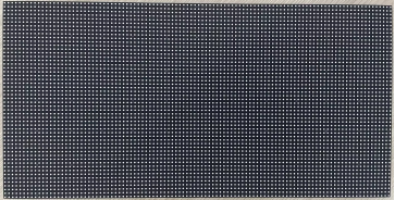
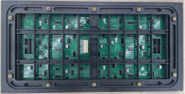
3.7 Module Images
face picture |
| Remark: The driver chip used is an SSOP packaged constant current driver chip. |
Back view |
| |
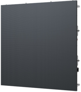
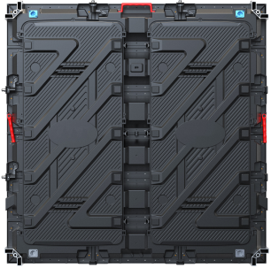
3.8 . Recommended 960*960 cabinet model
Front view | Rear view |
|
|
4. Product Technical Requirements
4.1. Screen Technical Parameters
brightness | ≥5000 cd/㎡ | Brightness uniformity | >0.95 |
Screen horizontal viewing angle | 140±10 degrees | Screen vertical viewing angle | 130±10 degrees |
Optimal viewing distance | ≥ 5.4 m | Usage Environment | outdoor |
Maximum power per square meter of module | ≤ 585 W/㎡ | ||
Power distribution capacity (maximum power per square meter ÷ 78% ÷ 85% ) | ≤ 883 W/ m² | ||
Gray levels | , green, and blue each 14-15 bits | Display color | 4.398 trillion species |
Frame rate | ≥60 frames/second | refresh rate | 7680 Hz |
Control method | Computer-controlled, point-to-point correspondence, video synchronization, real-time display | Brightness adjustment | 256 levels manual/automatic |
Input signal | DVI/VGA/HDMI/DP, composite video signal, S-VIDEO, YPbPr (HDTV) | ||
Mean Time Between Failures | ≥ 5000 hours | ||
Operating temperature range | -20-40℃ | Operating humidity range | 10% -90 %RH |
Protective performance | Over-temperature/overload/power failure/image compensation/various correction technologies/overcurrent/overvoltage/lightning protection (optional) | ||
Screen flatness | <1mm/㎡ | ||
Screen vertical flatness | <1mm/㎡ | ||
4.2. Enclosure Technical Parameters
Box dimensions ( length * width * thickness ) | 960mm*960mm*104.5mm (thickness includes modules and housing) 960mm*960mm*169.5mm (thickness includes modules, housing, and connecting pieces) |
Speaker resolution | 312 * 312 = 97344 Dots |
Box area | 0.9216 ㎡ |
Box weight | 29.7 kg ± 0.5 kg |
Maximum power consumption (module power * number of modules in one enclosure) | ≤ 540 W |
Average power consumption (1/3 of maximum power) | ≤ 180 W |
Power distribution capacity (power utilization rate 78%, i.e., maximum power ÷ 78%) | ≤ 692 W |
4.3. Module Technical Parameters
pixel pitch | 3.0 mm | Pixel density | 105625 Dots/㎡ |
Pixel composition | 1R1G1B | Lamp tube packaging | SMD 1515 |
Dimensions (Length * Width * Thickness) | 320*160*1 7.5 mm | weight | 0.40 kg ± 0.01 kg |
Structural features | Integrated lamp and driver | Module resolution | 104 * 52 = 5408 Dots |
Input voltage (DC) | -3.2V/-4.0V (Dual negative pressure input) | Maximum current | R ≤ 2.8 A GB ≤ 5.2A |
Module power | ≤ 30 W | driving method | 1/1 3 Constant Current Drive |
Number of modules in 20A/30A power supply ( Requires the use of a DPS energy-saving power supply ) | 3-4 pictures | Number of modules supported by 30A / 40A power supply ( Requires the use of a DPS energy-saving power supply ) | 5-6 pictures |
5. Module signal interface definition
pin | Signal | Function | pin | Signal | Function |
1 | RD1 | Red data signal | 2 | GD1 | Green data signal |
3 | BD1 | Blue data signal | 4 | GND | power ground |
5 | RD2 | Red data signal | 6 | GD2 | Green data signal |
7 | BD2 | Blue data signal | 8 | GND | power ground |
9 | A | Power control signal | 10 | B | Power control signal |
11 | C | Power control signal | 12 | D | Power control signal |
13 | CLK | clock signal | 14 | LAT | Data latch signal |
15 | OE | Enable signal | 16 | GND | power ground |
 HUB 75
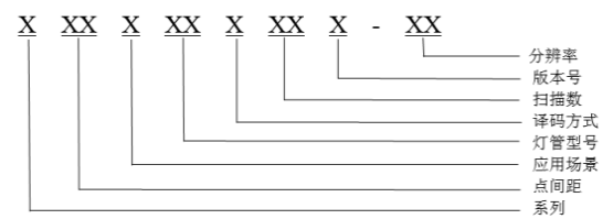
6. Product Model Naming Instructions
7. Installation Hole Location Diagram
7.1. Module mounting holes:
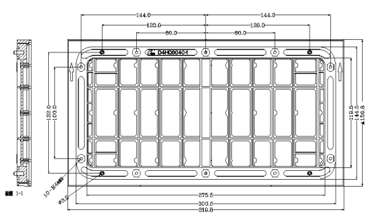
Note: "If a cabinet is required, please inform the office in advance and confirm the hole layout drawing for the order. Please refer to the CAD drawing for details."
All dimensions are in mm .
7.2. Recommended mounting hole layout for 960 * 960 enclosure:
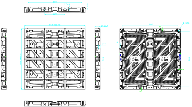
Remark: All dimensions are in mm.
8. Installation Guide
8.1. Power supply and module wiring diagram (This diagram is for reference only; please refer to the actual product for specific wiring methods):
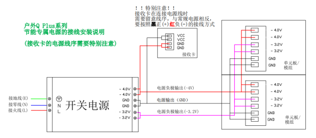
PS: The power supply and connecting cables must be used with DPS energy-saving power supplies and connecting cables.
8.2 . Installation Overview :
8.2.1. Six common installation methods for outdoor display screens.
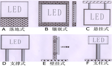
The cabinets should be installed starting from the bottom layer. Avoid haphazard installation, as this will affect the display effect. During installation, ensure the bottom layer is perfectly flat before installing the upper cabinets. Apply waterproof sealant to the joints between cabinets. After the entire screen is tested, thoroughly waterproof the entire screen structure .
8.3. Acceptance requirements and methods for display screens:
8.3.1. Screen Brightness: Set the screen to full brightness. On the computer, adjust the brightness efficiency in the testing software to 80%. Within 10 minutes, use a light gun to measure the screen brightness . When measuring brightness , the light gun must be aimed directly at the screen, ideally level with it . Ensure that the black area in the observation window covers at least 16 pixels. Adjust the focus for measurement.
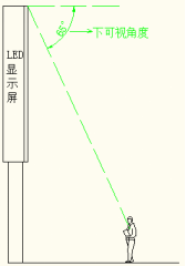
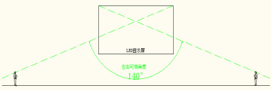
8.3.2. Viewing angle: When measuring, the person stands at a position 140° to the left and right of the screen and at a position 65° below the screen. The screen should be free of obvious black spots and dark patches.
8.3.3. Grounding: The switching power supply casing, enclosure, and panel structure are correctly grounded, and the grounding point is correctly marked with the grounding mark . An inspection shall be conducted every six months.
8.3.4. Lightning protection: Buildings are required to have lightning rods or lightning protection strips with effective grounding. Distribution boxes are required to be equipped with surge protectors . Lightning protection facilities shall be inspected every six months .